Auto Power Swich
 Switch on your pc when power applied, not by pushing a button. Originally designed for EPIA MS8000 Mini ITX motherboard, this baby will switch your pc on when eve it gets power.
Description:
A replacement for the momentary action switch on the front of a of a PC this detects the power being restored to the PC waits a second and a half and then pops the power switch automatically. Great for home built servers that you want to turn on when power is restored. Or in out case when its in a Waterproof box up a tree in Glastonbury.
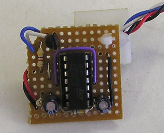
PARTS:
- Strip board
- CMOS Quad NAND gate Chip (4011)
- 2.2μF Capacitor
- 4.7μF Capacitor
- 1MΩ 0.25W Resistor
- 560kΩ 0.25W Resistor
- 4.7kΩ 0.25W Resistor
- BC549B NPN Transistor (or similar)
- 1 Reset/Pwr Switch case wire.
- 1 case speaker wire.
- Couple of bits of wire (single strand insulated for preference)
- Self Adhesive PCB mount (optional)
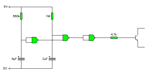
Circuit Diagram
How it Works:
The Resistors on the left charge the capacitors up. When the capacitors get above 2.5 volts the NAND gate's detect their inputs going from low to high. The left hand NAND above is configured as a NOT gate, so when power is applied to the circuit its inputs are low and its output high. The Middle NAND gate is receiving at startup a low from its resistor capacitor and and a high from the left hand NAND. After about 1.5 seconds the right hand capacitor has reached 2.5 volts, turning the middle NAND gates inputs to HIGH and HIGH, as the left hand capacitor takes longer to reach 2.5 volts. The left hand capacitor takes about .25 seconds longer to reach 2.5 volts, when it does the middle NAND goes back to HIGH low. IF we look at the truth table for a NAND (Not And) gate:
|
Input 1
|
Input 2
|
output
|
|---|---|---|
|
0
|
0
|
1
|
|
0
|
1
|
1
|
|
1
|
0
|
1
|
|
1
|
1
|
0
|
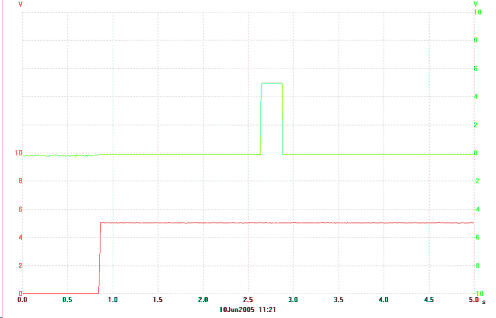 We can see that a NAND gives out a low, only when BOTH its inputs are high. In this case that only occurs when one capacitor has reached 2.5 volts and the other has not. This gives us the wait for 1.5 then switch the pc on, nut don't hold the button in signal we want. Unfortunately its the wrong way up. On power up the middle NAND gives out high for 1.5 seconds, then low for a quarter second then goes high again. To drive the transistor on the right we want he opposite, so we use another NAND with its inputs hooked together to make a NOT gate. The 4.7k resistor is to limit the current into the base of the transistor. The Image shown on the right is a dual trace PC oscilloscope. the Lower, red, trace is the power supply coming in. The green trace the output to the transistor switch on the right, which is connected to the switch header of the PC.
Connections
On the Mini ITX boards we're using, the keyboard and mouse header has the ITX always on power supplied to it. We use pins 2 and six, because their easy to spot, separated as they are by the blank key slot. We use an old PC case speaker connector, with the pins moved from 1 and 4 to one and 3. If you want you can cut off the extra slot too, if it makes you feel better.
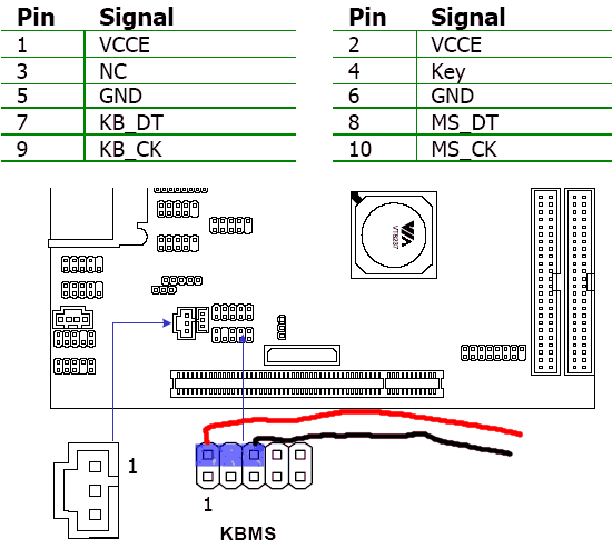
EPIA MS8000 mother board Keyboard/Mouse header used as power supply.
If your running this off another type of motherboard you'll need to find your own source of always on 5 volts.
The on switch is easier, all you need to do is plug the thing in instead of the switch NOTE, I'm not sure abut this but I think the current has to flow the right way through the transistor. The +ve side of the switch there for, needs to be attached to the COLECTOR, top of my circuit diagram, emitter, the one with the little arrow on the bottom of my circuit diagram to ground. Pins 6 and 8 respectively:
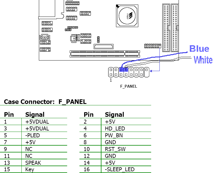
EPIA MS8000 Power Switch Header
Construction
Well that's relatively easy, I'll add the strip board layout when I have time to draw it on a PC. The only things you really need to look out for are:
- Capacitors are POLORISED, that means they need to be connected the right way round, the negative leg is marked by a strip with "-" on it on the case.
- Chips need power, these are customarily left out of the circuit diagram for clarity, as they are in this case. Pin 14 needs +5 volts and pin 7 0 volts.
- Transistors have different pinnouts, make sure you get yours with the resistor on the base, and the outputs on the collector and emitter.